Study for the technical solution for linings for the bio boiler of the heating plant in Hodonín
home Articles Study for the technical solution for linings for the bio boiler of the heating plant in Hodonín
In this article, we will focus on the study of the technical solution of the boiler linings in the Hodonín heating plant, which was prepared by DITHERM specialists and was handed over to the customer prior to launching. We will focus mainly on the influences that affect the lining, the mechanical influences and the like.
CHEMICAL AND PHYSICAL CHARACTERISTICS AFFECTING LININGS IN BOILERS
Boiler linings have many influences that can be simply divided into chemical and physical. Chemical effects are mainly due to the combustion of flue gases from individual fuel types. Physical phenomena include, in particular, the temperature and mechanical stress of the linings. In some parts of the lining, both influences act at one and the same time, therefore, it is necessary to carefully choose the lining material used in normal and general repairs and investment works on linings.
Chemical effects on linings
At the Hodonín power station, fossil fuels, wood chips and biomass are burned in fluidized bed boilers. Individual fuels have a different chemical composition of combustion gases, which affect the linings differently. Various additives are added to the fuel in order to eliminate the negative components of flue gas emitted into the air.
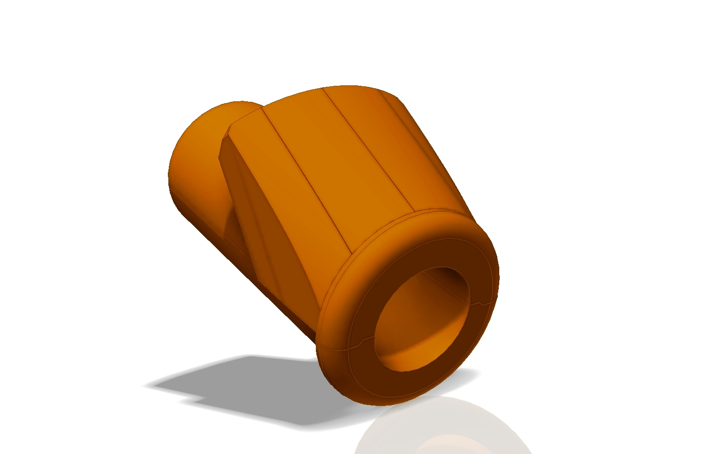
Innovative design of burner casing
Chemical effects on linings during biomass combustion
From the documents we received in the process of the assessment of the lining condition in October 2010 on the composition of the biomass burned in the FK2 boiler at the Hodonín power station, it is clear that the biomass contains wood chips and granulate from vegetable waste including, for example, sorrel, sunflower expector, grain, rapeseed straw, wheat bran, rye bran, etc. In the combustion of these fuels, especially potassium compounds are formed, which occur in the form of vapours at temperatures between 800 and 900 °C. Pairs of potassium compounds migrate into the lining and, together with other compounds (sodium, calcium) in the form of chlorides, sulphates, carbonates, etc., cause alkaline corrosion and lining damage. Alkaline corrosion is characterized by the peeling of the surface layers, the cracking, the bending of the individual lining pieces, the bulging of the entire walls and their sliding components. These forms of damage do not usually occur in the entire volume of the lining built in, but only in some zones, usually with a temperature between 800 to 900°C, which is practically in all zones in the case of a fluid boiler. From the experience of repairing FK2 in 2009, Hodonín power station was most affected by alkaline corrosion in cyclones. The lining of the working layer peeled off at a thickness of about 30 mm. The cause of alkaline corrosion is the reaction of alkaline compounds with some components of the refractory lining, which gives rise to new compounds having a larger volume than the original compounds. According to the published data, the volume differences are between 7 and 30 %, which means the lining penetrates the tension, which leads to facial defects. Alkalines migrate into the lining, in particular in the form of vapour, which means that faults occur even in places that are not in direct contact with ash. The influence of alkalis on the lining is constantly acting, that is, the alkali acts on the damaged lining, and the degradation continues until the total degradation of the lining occurs, which already causes the aggregate to fail. Alkaline corrosion is a very aggressive chemical process, and total lining degradation occurs in a very short time.
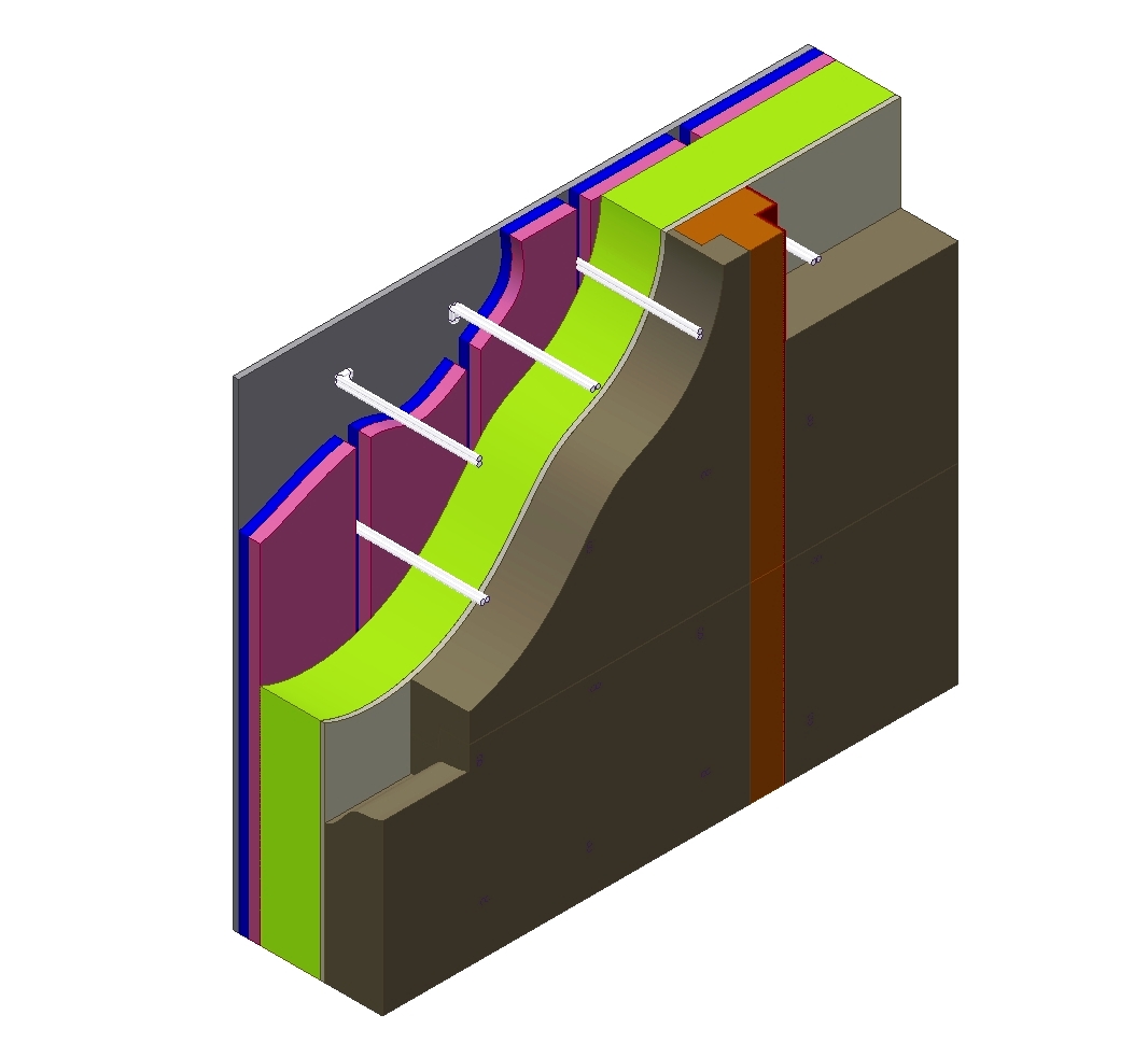 Detailed cross-section of the lining walls
PHYSICAL EFFECTS ON THE LININGS
Thermal effects on lining
The lining is negatively affected by significant temperature changes in a short time, such as fast start-ups, starting up the unit after repairing when the drying curve is not followed, forced cooling of the linings. To eliminate these influences, it is necessary to first control the aggregate after the lining repair or after a cold shutdown, according to a set drying and tempering curve.
Drying and tempering of linings after repair are carried out in order to remove water from the lining materials. Failure to observe the drying and tempering curves can result in cracks in the lining, which can lead to faster degradation of the linings and in extreme cases, the boiler can even be destroyed. Damage to linings in this case causes the release of water, whether loose at lower drying curve temperatures, or chemically bonded at higher temperatures of the start-up curve. Drying of linings prevents hardening of the lining material, when a portion of free water spontaneously evaporates. If the unit was only in a cold shutdown, it is necessary to observe the tempering curve. Tempering of the linings serves to evenly heat the lining materials in order to avoid cracks or degradation of the linings due to the thermal expansion of the lining material.
Mechanical effects on the lining
Mechanically, the lining in the fluidized bed boilers is mainly affected by abrasion. Abrasion causes flow of ash in individual parts of the boiler. Most of the abrasions are stressed by walls and ceilings in cyclones, lead from cyclones to siphons, lining in siphons, fuel ducts to the combustion chamber and channels from the combustion chamber to the coolers.
CONDITION OF FK2 BEFORE RENOVATION
The FK2 boiler currently burns 100 % biomass. The lining in the FK2 boiler is designed for burning fossil fuels. Biomass is very chemically aggressive to the current lining, so there are specific damages with respect to the combustion fuel. In 2009, most of this damage occurred in cyclones, where the lining peeled off. Further damage can be expected during further shutdowns from the penetration of alkali into linings. Other serious damage to the linings occurs in the bed ash channels from the combustion chamber to the coolers. The influence of alkaline corrosion on the linings in the FK2 fluid bed boiler is based on the chemical analysis of the removed lining.
REPAIR TECHNICAL SOLUTION
In solving the new repair solution, we relied on the need to reconstruct or renovate the working layers of the linings, taking into account the combustion fuel. For the working lining, it is necessary to choose the low-alumina-resistant, low-cement concrete and, in specific parts, abrasion-resistant (hereinafter referred to as LCC refractory). To ensure resilience to planned cold shutdowns, all concrete in the working part of liners containing stainless steel fibres will make the refractory tougher and compensate for its stresses when cooling and starting the boiler. The anchoring of the lining will be carried out with CTH anchors of a 10 mm diameter made of AISI 330, which will be provided with expansion caps. The dilatation caps are used to compensate for the different thermal expansion of the concrete and the material from which the anchors are made. There will be approx. 22 anchors per square metre.
Bottom of the combustion chamber
The bottom of the combustion chamber will be completely replaced during the general repairs, including the steel structure. The technical design of the bottom of the combustion chamber floor was chosen after co-ordination with the steel contractor. The bottom of the combustion chamber forms at the bottom the steel structure of the air chamber, from which the air nozzles emanate. The fluid bed is made with low cement refractory concrete (LCC). The new technical solution is structurally coincident with the existing solution, and the lining material will be a self-flowing low-cement refractory concrete. Self-flow concrete was chosen because of the impossibility of vibrating in this part of the boiler.
The repair of the fluidized bed will involve work on the steel construction and lining, in this part of the boiler it is necessary to efficiently co-ordinate all of the supply companies. First, the linings are dismantled on the walls of the combustion chamber, and the liner of the fluidized bed will then be removed. After dismantling the linings, a repair of the steel structure of the fluid bed will be carried out. After the steel structure is assembled, a new fluid bed liner will be installed, followed by a technological break where the concrete is cured to the point where the fluidized bed can be protected by overlapping in order to prevent clogging of the nozzles and then the lining of the combustion chamber walls.
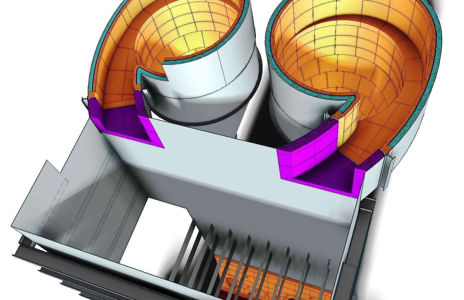
View of the cyclones and the combustion chamber of the FK2 boiler
Walls of the combustion chamber
The walls of the combustion chamber will form a multilayer lining. A special low-cement refractory concrete, alkali-resistant, will be used on the working layer. In order to meet the technical standards, a new structure of insulating linings was proposed for the study of the technical solution. Microporous insulating boards will be used on the casing of the combustion chamber, the next layer of insulating lining will use insulating chamottes with insulation made of insulating concrete.
The composition of the lining:
Spec. refractory LCC. . . . . . . . . . . . . .. .120 mm
Insulating refractory concrete. . . . . . . .. .15 mm
Insulating fittings. . . . . . . . . . . . . . . . .. .125 mm
Micro-porous plates . . . . . . . . . . . . . . . .40 mm
Total thickness . . . . . . . . . . . . . . . . . . .300 mm
The layout of the linings ensures that the temperature of the boiler shell is at a maximum of 65°C. Removal of linings on the walls of the combustion chamber will take place before dismantling the bottom of the combustion chamber. The removal of the linings will prevent the installation of the scaffolding around the combustion chamber circumference up to the height of the cyclones in the combustion chamber, due to the dismantling of the linings in the opening. After dismantling the walls of the combustion chamber, the scaffolding will be dismantled, and the dismantling of the bottom of the combustion chamber will proceed. After the production of the new combustion chamber bottom linings and the technological break for solidification of the combustion chamber linings, the scaffolding will be assembled, the anchoring of the anchor elements and the linings will be assembled in the above-mentioned structure.
Channels from the combustion chamber to the coolers
In the FK2 fluid boiler, there are five ash bed coolers on each boiler. The bottom channel from the combustion chamber to the radiator serves to drain the ash from the combustion chamber into the radiator. The channel diameter in the combustion chamber is 150 mm, and the radius in the cooler is 200 mm. These channels are currently very degraded, the lining is out of date. The lining is falling apart. The last repairs were in 2009, and were made with a new, provisional, technical solution. During these repairs, the installation of the monolithic lining from the LCC of the refractory concrete was repaired after the cascade ash shifters. However, this technical solution is provisional and increases the temperature on the heat sink shell by about 100°C. For the general repair, these channels must be rebuilt.
To reconstruct these channels, we propose the following technical solution. Due to the space, we chose a double-layered lining. As an insulating layer, we propose insulating refractory concrete and the working layer will be made of self-flowing refractory concrete into an alkali-resistant shuttering and with high abrasion resistance. We have chosen a high abrasion resistance material because high-velocity fly ash from the combustion chamber flows into the cooler in this channel, and there is a turbulent flow.
The composition of the lining:
Self-flowing refractory LCC. . . . . . . . .100 mm
Insulating refractory concrete. . . . . . . .50 mm
Total thickness. . . . . . . . . . . . . . . . . . .150 mm
Because of the low lining thickness, the jacket temperature is about 170°C, so it will be necessary to take precautions to prevent the boiler operator from accessing the boiler during operation. Another requirement for the ash channels was to propose a technical solution for separating coolers. This can only be carried out in a way that can be done without mechanical intervention into the boiler. The solution proposed by us envisages the separation of the heat sinks at the boiler shutdown, by making concrete radiator plugs (“corks”), which are secured against loosening in the ash coolers. The plugs will be made of special alkali corrosion resistant LCC, so they will be inserted into the ash bed channel. Stoppers will be provided on the plugs to prevent the plugs from moving into the channels.
The top channel from the radiators to the combustion chamber serves as a discharge of the unburnt ash back into the combustion chamber. These channels are in relatively good condition, but with regard to the chemical environment in the boiler, the general repair of the combustion chamber lining and the radiator plug solution, we chose complete reconstruction. The top cooler channel has a lining thickness of 150 mm. The channel diameter is 900 mm and for this reason, it is possible to use a microporous material that is better heat-insulating as an insulating layer, so this lining will suit the surface temperature of the shell without special external locking. The LCC refractory lining resistant to alkalis and abrasion will be used on the lining work. The upper channel closures of the coolers will be executed in the same way as in the lower ash channels.
The composition of the lining:
Self-flowing refractory LCC. . . . . . . . .100 mm
Microporous plates. . . . . . . . . . . . . . .. .50 mm
Total thickness . . . . . . . . . . . . . . . . . .150 mm
Inlet ductwork, cyclones
The walls of the flue gas ducts will form a multi-layer lining. The working layer is designed with low-cement refractory concrete that is abrasion-resistant and alkali-resistant as the exhaust ducts flow into the ash cyclones and abrades on the working layer of the lining. The insulating lining is designed from several layers, the microporous plates will be installed on the flue gas duct, the second insulating layer from the shell will form insulating chamotte shaped pieces and the insulating fittings will be made of insulating concrete.
Lining composition:
Spec. refractory LCC. . . . . . . . . . . .. .120 mm
Insulating refractory concrete. . . . .. .. .15 mm
Insulating fittings. . . . . . . . . . . . . . ... .125 mm
Microporous plates. . . . . . . . . . . . . .. . .40 mm
Total thickness. . . . . . . . . . . . . . . . . . .300 mm.
The same lining composition should also be for the floor, but we do not expect to repair this part of the lining during the general repairs. The ceiling of the exhaust ducts will form a three-layer lining. The working layer will be formed from LCC concrete with high abrasion and alkali resistance, vibrated into the formwork through the holes burned in the lining jacket, which will also facilitate the removal of water vapour during drying of the linings. The insulating layer of the lining on the shell will be formed by microporous plates and between the plates, and the work lining will be exposed insulating refractory concrete.
Lining composition:
Spec. refractory LCC. . . . . . . . . . . . . .120 mm
Insulating refractory concrete. . . . .. . .140 mm
Microporous plates. . . . . . . . . . . . . .. . .40 mm
Total thickness. . . . . . . . . . . . . . . . . . .300 mm
The above-mentioned lining compositions provide a maximum jacket temperature of 65°C.
Leads from the cyclone to the siphon and from the siphons to the combustion chamber
Fuel jets are, according to the condition from repairs in 2009, in a relatively good condition, we expect repairs of about 30 % of the lining. The actual area is determined by the condition of the linings after further operation of the aggregate. Fuel jets will be made with three layers of linings. One working and two insulating. The thickness of the lining is 300 mm. The working lining will be resistant to alkali and abrasion, from the LCC. These parts of the boiler return the ash through the siphons into the combustion chamber and abrasively affect the lining. The insulating layer on the shell will be made of microporous plates, the next insulation layer will be torkreted insulating refractory concrete. This lining composition guarantees the surface temperature of the jacket at the temperature required by the technical standards.
Lining composition:
Spec. refractory LCC. . . . . . . . . . . . . .120 mm
Insulating refractory concrete. . . . . . . .140 mm
Microporous plates. . . . . . . . . . . . . . . . .40 mm
Total thickness . . . . . . . . . . . . . . . . . . .300 mm
Compensators under the siphons are currently made on a steel structure, on which the welded anchors and the lining are formed by torkreting of the refractory concrete. The construction of the compensator is satisfactory, only the torkreted refractory concrete would be used in the overhaul of the concrete, which is resistant to alkaline corrosion and abrasion because of the lower porosity, so the danger of alkali penetration is smaller.
Siphons
Siphons (also fluid shutters) serve to direct the flue gas flow from siphons to the combustion chamber. In the siphons, there are linings on the bottom, where there are nozzles, the lining of the bottom is formed by self-flowing concrete. We do not expect any repairs in this part of the siphon. The siphon walls form a working lining, here we propose refractory LCC resistant to alkaline corrosion and abrasion, because this part of the boiler is swirling ash, and therefore is also under higher mechanical stress. On the insulating lining, we designed microporous plates to be installed on the boiler shell. The other insulating layer will be insulating chamotte shaped pieces, which will be insulated with refractory concrete.
Lining composition:
Spec. refractory LCC. . . . . . . . . . . . ..120 mm
Insulating refractory concrete. . . . . . . .15 mm
Insulating fittings. . . . . . . . . . . . . .. . . .125 mm
Microporous plates. . . . . . . . . . . . . . . .40 mm
Total thickness. . . . . . . . . . . . . . . . . . .300 mm
The lining structure provides a maximum surface temperature of 65°C for the shell, which is required by technical standards. We designed the lining of the siphon from refractory LCC to be resistant to alkaline corrosion and abrasion. The insulating lining will be formed on the boiler shell by microporous plates, the second insulating layer will be formed from insulating refractory concrete.
Exhaust gas ducts
Exhaust ducts are connected to the cyclones. Exhaust gas ducts are evacuated by exhaust gases, which are separated in cyclones from fly ash. The flue gas is fed from the exhaust ducts to the second boiler flue. Only exhaust gases with minimum fine fly ash are discharged into the exhaust ducts, and there is no mechanical abrasion. That’s why we have selected LCC refractory resistant to alkali corrosion for the lining work. The insulating layers of the wall lining will be formed by a microporous plate on the boiler shell. The other insulating layer will be made of insulating chamotte blocks with insulating concrete. Spec. LCC refractory 120 mm, insulating refractory concrete 15 mm, insulating fittings 125 mm, microporous plates 40 mm. Total thickness 300 mm.
Microporous plates and insulating refractory concrete will be used on the casing.
Lining composition:
Spec. refractory LCC. . . . . . . . . . . . . .120 mm
Insulating refractory concrete. . . . . . .140 mm
Microporous plates. . . . . . . . . . . . . . . .40 mm
Total thickness. . . . . . . . . . . . . . . . . . .300 mm
The designed linings will ensure the maximum surface temperature on the boiler shell of 65°C, as required by technical standards.
Ash coolers
The linings of the ash coolers are made of a 200 mm lining. In this part of the boiler, we assume a lower operating temperature, therefore the designed lining composition will meet the technical standards, and the shell temperature will be at maximum 65 ° C. In this part of the boiler, there are defects in connecting the lower channels from the combustion chamber. This damage eliminates the addition of stainless needles to the mixture of refractory concrete. Both the ceiling and the walls of the bed ash coolers will be formed from the same lining composition. In the working layer, we used LCC refractory with alkali corrosion resistance. The insulating layer will be formed on the casing with a microporous plate, and the second insulating layer will be formed from torkreted insulating concrete.
Lining composition:
Spec. refractory LCC. . . . . . . . . . . .. . .100 mm
Insulating refractory concrete. . . . . . .. . .60 mm
Microporous plates. . . . . . . . . . . . . .. . . .40 mm
Total thickness . . . . . . . . . . . . . . . . . . .200 mm
SUMMARY OF THE TECHNICAL PART
The concept of our lining design takes into account the changed operating conditions of the two fluid boilers, which are mentioned in the introduction to this document. For this reason, after consultation with the producers of refractory concrete materials and based on the results of the development of new material mixtures, we have designed special LCC alkali resistant refractories for the layers of working linings in some parts, with increased abrasion resistance. As a consequence of the change of working layer materials, it will be necessary to change the shape and structure of the dilatation fields in some passages, depending on the different temperature-dependent volume changes of the newly used materials. At the same time, we propose incorporating needles made of heat-resistant steel into the mixture, which will ensure a higher toughness of the refractory mass, and therefore better mechanical properties for the planned number of boiler cold shutdowns.
TOTAL QUANTITIES OF APPLIED MATERIALS FOR LINING FK2 BOILER
- CONCRETE 210 tons
- INSULATION KNOB 37,500 pieces
- SPECIAL INSULATION PLATES 1,650 m2
- ANCHORS 13,500 pieces
We also propose polypropylene fibres to be added to the blends, to ensure faster water vapour extraction from linings after installation and any future repairs. With respect to the reduction of surface temperatures in the non-pressure parts of the boiler, we have, in some parts, modified the composition of the insulation layers. At places where temperature conditions allow, we applied an insulating layer of microporous material on the inner side of the shell, which has excellent insulation properties, compared to conventional insulating materials of similar application. This solution reduces heat losses, while reducing the surface temperature in some parts of the plant.
Roman Fišer, Ing. Mojmír Nesvačil, DITHERM a.s.